High-capacity drilled foundations socketed to bedrock.
Drilled Shafts
We install drilled shafts — augered, cased, and rock-socketed — for high-capacity foundations where heavy column loads must reach competent strata or bedrock with low vibration near adjacent structures.
Cross-section
Callouts
Select a numbered part below to read what it is and what it does.
- Steel casing stabilizes the bore through caving fill and soft clay; it is withdrawn or left in place as the shaft is concreted.
- A full-length cage of longitudinal bars and spiral ties is lowered into the bore before concrete placement to carry bending and tension.
- Concrete is placed from the base up, displacing any slurry to produce a sound, continuous, high-capacity shaft.
- The shaft is socketed into argillite bedrock to develop very high end bearing and side resistance for heavy column loads or uplift.
Typical spec
Plain-language view of the same typical ranges.
- Shaft width
- 24–72 in
- Diameter of the drilled foundation.Diameter sized for axial/lateral demand; reduced socket diameter common below the casing.
- How deep it goes
- 30–100+ ft
- Typical depth to competent rock.Length set to reach socket elevation; side + base resistance develop the capacity.
- Keyed into rock
- Into argillite/bedrock
- The shaft is drilled into bedrock.Socket length from rock side-shear & end bearing; cores/probes confirm rock quality.
- How much it holds
- ≈ 200–1,000+ tons
- Designed for very heavy column loads.High allowable capacity from rock socket; design vs service loads checked, FoS applied.
How it goes in
- 01
Drill & case
The shaft is augered and temporary casing is set as needed to stabilize the bore through fill and clay.
- 02
Socket into rock
The bore is advanced into glacial till or socketed into bedrock to develop end bearing and side resistance.
- 03
Place rebar & concrete
A reinforcing cage is set and the shaft is concreted, displacing any slurry to produce a sound, continuous shaft.
Equipment on this work
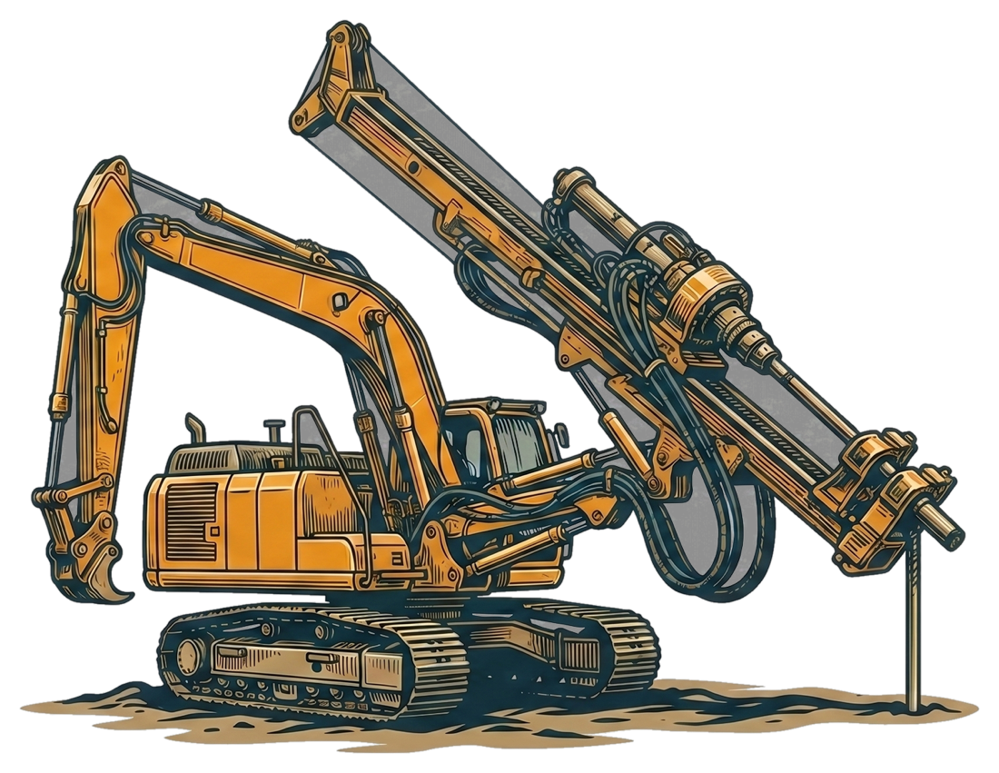
Klemm KR 806-3GS
Limited-access anchor & micropile drill
Advances and cases the shaft, then sockets it into rock.
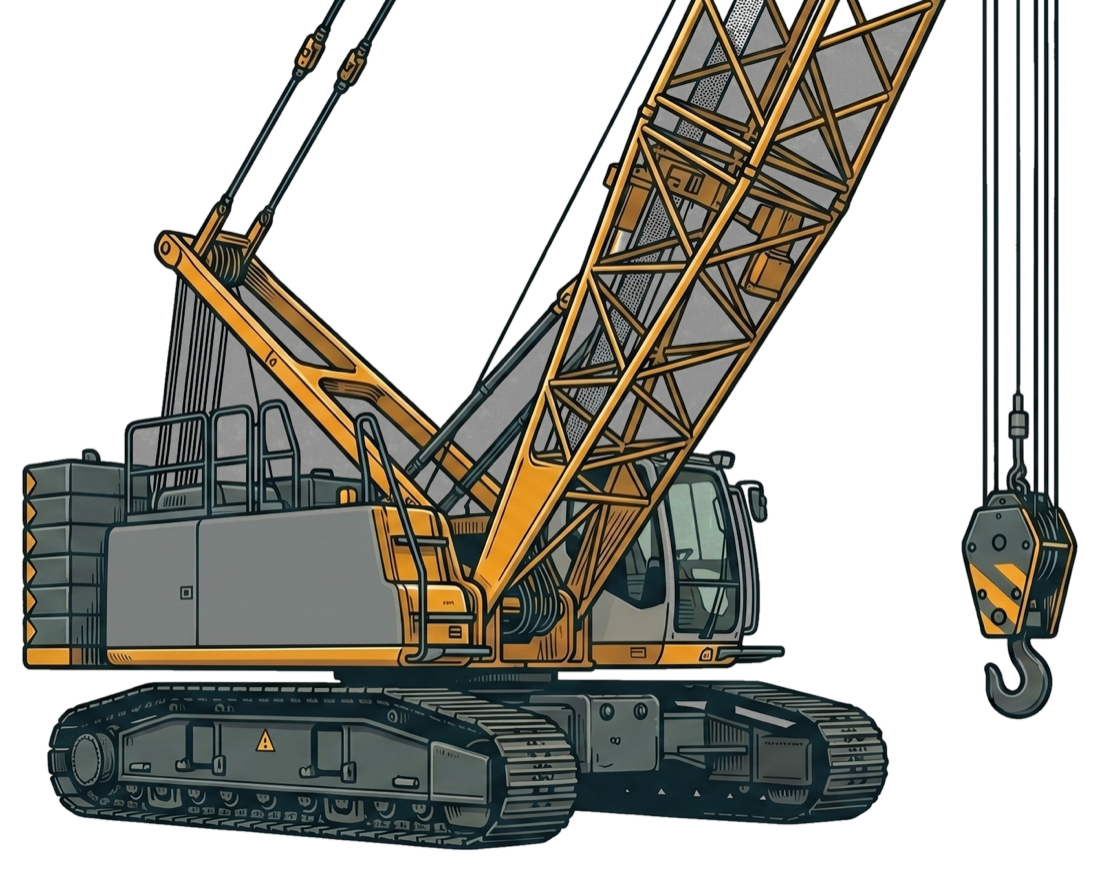
Liebherr LR 1130
Crawler service crane
Sets the reinforcement cage and handles the tremie.
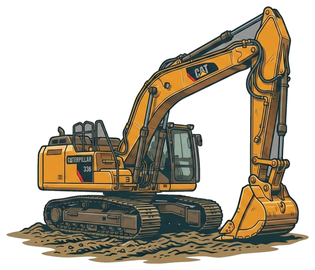
Caterpillar 336
Tracked hydraulic excavator
Moves spoils and keeps a level working platform.
Equipment shown as illustrative renderings.
Where it fits
- Heavily loaded columns and towers
- Foundations requiring rock sockets
- Low-vibration installation near neighbors
- Bridge and infrastructure foundations
Frequently asked
Related projects
Illustrative tear sheets — example case studies pending verification.
Ready to scope your foundation?
Tell us about the project and we'll put together a detailed quote within 3 days. We generally work with general contractors.
Or email plans to bids@earthsupportcorp.com