
Reinforce foundations and tie back retention systems.
Anchors
Our expert team installs reliable soil and rock anchors including ground, helical and micropiles to reinforce foundations.
Cross-section
Callouts
Select a numbered part below to read what it is and what it does.
- Where the stressed tendon locks off and transfers its tension into the wall; the lock-off load is set as a percentage of the proof/test load.
- Sheathed tendon that carries no soil load; it extends beyond the potential failure wedge so capacity develops only in stable ground.
- A soil anchor bonds in overburden; a rock anchor sockets into competent bedrock, generally allowing higher design loads — typically 30–150 kips — over a shorter bond.
- A small-diameter (5–12 in) drilled-and-grouted pile used where access or headroom is tight; it carries high axial load to deep competent strata.
- The grouted length keyed into argillite bedrock, developing high side resistance and end bearing for uplift or compression.
Typical spec
Plain-language view of the same typical ranges.
- Grip length in the ground
- 15–40 ft
- The grouted length that holds the anchor.Bond length sized for grout-ground bond stress & required design load with a factor of safety.
- Micropile thickness
- 5–12 in
- Diameter of the small high-capacity piles.Drill-hole diameter governs bond area and casing; high capacity from steel + grout composite.
- How much it can hold
- 30–150 kips
- The typical working load range per anchor.Design (factored) load vs service load distinguished; anchors proof/performance-tested above design.
- Locked-in tension
- Per design (% of test load)
- The load left in the anchor after stressing.Lock-off set as a % of test load to control wall movement; verified by lift-off testing.
How it goes in
- 01
Drill the bore
A cased or open hole is drilled to the design depth through the no-load zone and into competent ground.
- 02
Install the tendon
A steel tendon or bar is placed and grouted along the bond length to transfer load to the soil or rock.
- 03
Stress & lock off
Once grout strength is reached, the anchor is tested and stressed to its lock-off load.
Equipment on this work
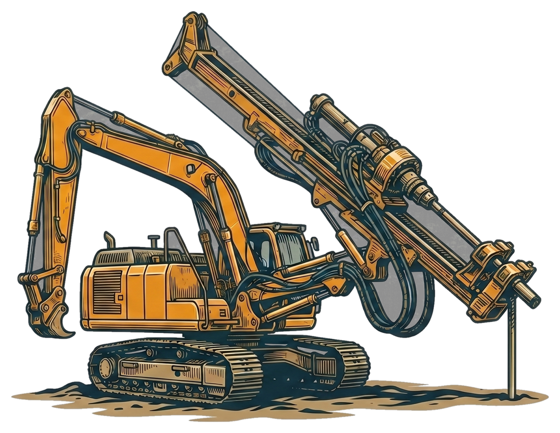
Klemm KR 806-3GS
Limited-access anchor & micropile drill
Drills the bore, installs the tendon and grouts the bond zone.
Equipment shown as illustrative renderings.
Where it fits
- Tieback support for retention walls
- Resisting uplift and overturning
- Slope stabilization
- Underpinning load transfer (micropiles)
Frequently asked
Related projects
Illustrative tear sheets — example case studies pending verification.
Ready to scope your foundation?
Tell us about the project and we'll put together a detailed quote within 3 days. We generally work with general contractors.
Or email plans to bids@earthsupportcorp.com